


Send Message
Faʻalauaiteleina Faʻamatalaga: E taua tele lou faʻalilolilo ia te i tatou. E le faailoaina e le ma kamupani ia oe lava faʻamatalaga i soʻo se mea e faʻatagaina ai lau faʻatagaga.
Faataʻitaʻiga No.: NSO4GU3AB
Felauaiga: Ocean,Air,Express,Land
Totogi totogi: L/C,T/T,D/A
Incoterm: FOB,EXW,CIF
4GB 1600MHZ 240-PIN DDR3 UDIMM
Faafoliga Talafaasolopito
|
Revision No. |
History |
Draft Date |
Remark |
|
1.0 |
Initial Release |
Apr. 2022 |
|
![]()
Okaina o faamatalaga
|
Model |
Density |
Speed |
Organization |
Component Composition |
|
NS04GU3AB |
4GB |
1600MHz |
512Mx64bit |
DDR3 256Mx8 *16 |
Faʻamatalaga
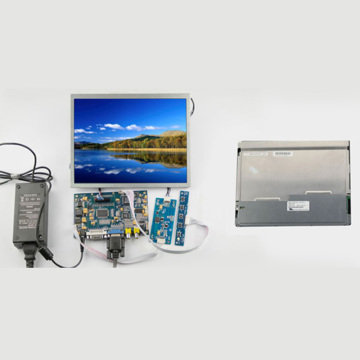
Hengstar Upbufred DDR3 SDRAM MONMSS (Unbufffered Daice Dism Cynchronous Deam Double Sweet Modules. NS04GI3AB o le 512m X 64-bit e lua tulaga 46b Ddr3-1600 CL11 1.5V sdred damm oloa, faavae i luga o le sefulu ma le ono 46m x 8-bit fbga. O le SPD o loʻo faagaoioia i Jedc Stande Lavency DDR3-1600 taimi o le 11-15-11 i le 1.5V. O le 240-PIN PRDM e faʻaaogaina le auro fefiloi tamatamailima. O le SDROC e le tatalaina le Dimem o loʻo fuafuaina mo le faʻaaogaina o le faʻamanatuina o le manatua pe a faʻapipiʻi i faiga e pei o polokalama pei o fale ma fale faigaluega.
Foliga
powe sapalaiina: VDD = 1.5V (1.425V i le 1.575v)
vDDQ = 1.5v (1.425v i le 1.575v)
800mhz fck mo 1600MB / sekone / pine
8 tutoatasi i totonu o le Faletupe
'ppitepleespuruty Capilly: 11, 10, 9, 8, 8, 6
iclampmalfuble faʻaopopo laʻasaga: 0, CL - 2, poʻo le CL - 1 Uati
8-bit muamua-falai
bous le umi: 8 (interleave e aunoa ma se tapulaʻa, lava ma le amataina o le tuatusi "000" e le faʻatagaina le toe faitau o le A12 poʻo le TRS]
BI-itu-faʻatonuga faʻamatalaga o le strobe
irnang (oe lava) coubration; Lotoifale Lava Candibration e ala i le ZQ PIN (RZQ: 240 Oim ± 1%)
na died faʻamuta le faʻaaogaina o le ODT PIN
average faʻaleleia le taimi 7.8us i lalo ifo o le vaega 85 ° C, 3.9s i le 85 ° C <95 ° C
Gisychronous toe setiina
ad ated faʻamatalaga-itput drive malosi
"e ala i le topogi
PCB: Maualuga 1.18 "(30mm)
rohs tausisia ma halosen-leai
Key Time Completers
|
MT/s |
tRCD(ns) |
tRP(ns) |
tRC(ns) |
CL-tRCD-tRP |
|
DDR3-1600 |
13.125 |
13.125 |
48.125 |
2011/11/11 |
Tuatusi laulau
|
Configuration |
Refresh count |
Row address |
Device bank address |
Device configuration |
Column Address |
Module rank address |
|
4GB |
8K |
32K A[14:0] |
8 BA[2:0] |
2Gb (256 Meg x 8) |
1K A[9:0] |
2 S#[1:0] |
Faapipii faamatalaga
|
Symbol |
Type |
Description |
|
Ax |
Input |
Address inputs: Provide the row address for ACTIVE commands, and the column |
|
BAx |
Input |
Bank address inputs: Define the device bank to which an ACTIVE, READ, WRITE, or |
|
CKx, |
Input |
Clock: Differential clock inputs. All control, command, and address input signals are |
|
CKEx |
Input |
Clock enable: Enables (registered HIGH) and disables (registered LOW) internal circuitry |
|
DMx |
Input |
Data mask (x8 devices only): DM is an input mask signal for write data. Input data is |
|
ODTx |
Input |
On-die termination: Enables (registered HIGH) and disables (registered LOW) |
|
Par_In |
Input |
Parity input: Parity bit for Ax, RAS#, CAS#, and WE#. |
|
RAS#, |
Input |
Command inputs: RAS#, CAS#, and WE# (along with S#) define the command being |
|
RESET# |
Input |
Reset: RESET# is an active LOW asychronous input that is connected to each DRAM and |
|
Sx# |
Input |
Chip select: Enables (registered LOW) and disables (registered HIGH) the command |
|
SAx |
Input |
Serial address inputs: Used to configure the temperature sensor/SPD EEPROM address |
|
SCL |
Input |
Serial |
|
CBx |
I/O |
Check bits: Used for system error detection and correction. |
|
DQx |
I/O |
Data input/output: Bidirectional data bus. |
|
DQSx, |
I/O |
Data strobe: Differential data strobes. Output with read data; edge-aligned with read data; |
|
SDA |
I/O |
Serial |
|
TDQSx, |
Output |
Redundant data strobe (x8 devices only): TDQS is enabled/disabled via the LOAD |
|
Err_Out# |
Output (open |
Parity error output: Parity error found on the command and address bus. |
|
EVENT# |
Output (open |
Temperature event: The EVENT# pin is asserted by the temperature sensor when critical |
|
VDD |
Supply |
Power supply: 1.35V (1.283–1.45V) backward-compatible to 1.5V (1.425–1.575V). The |
|
VDDSPD |
Supply |
Temperature sensor/SPD EEPROM power supply: 3.0–3.6V. |
|
VREFCA |
Supply |
Reference voltage: Control, command, and address VDD/2. |
|
VREFDQ |
Supply |
Reference voltage: DQ, DM VDD/2. |
|
VSS |
Supply |
Ground. |
|
VTT |
Supply |
Termination voltage: Used for control, command, and address VDD/2. |
|
NC |
– |
No connect: These pins are not connected on the module. |
|
NF |
– |
No function: These pins are connected within the module, but provide no functionality. |
FAAMATALAGA : O LE PING FAʻAMATALAGA FAʻAALIGA LUGA O SE UIGA O SE UIGA O LE FAʻAPITOA UMA FOʻI MO UMA DDR3 MODE. O pine uma na lisiina Me aua le lagolagoina i luga o lenei vaega. Vaʻai PIN faʻatulagaina tofiga mo faʻamatalaga faʻapitoa i lenei vaega.
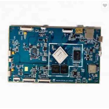
Polokalama poloka poloka
4GB, 512mx64 module (2rank o x8)


Module Fua
Manatu i luma

Manatu i luma

Faamatalaga:
1.Mill i luga o le milimita (inisi); Max / min pe masani (fiafia) o lea na matauina.
2.Faʻatasiga i luga o itu uma ± 0.15mmte seʻi vagana ai gaioiga faʻapitoa.
3. O le maimoa maimoaina o loʻo faʻasino atu naʻo.
Vaega Faʻatino : Alamanuia Smarma Module Meafaigaluega


Faʻalauaiteleina Faʻamatalaga: E taua tele lou faʻalilolilo ia te i tatou. E le faailoaina e le ma kamupani ia oe lava faʻamatalaga i soʻo se mea e faʻatagaina ai lau faʻatagaga.
Faatumu nisi faʻamatalaga ina ia mafai ona fesoʻotaʻi ma oe vave
Faʻalauaiteleina Faʻamatalaga: E taua tele lou faʻalilolilo ia te i tatou. E le faailoaina e le ma kamupani ia oe lava faʻamatalaga i soʻo se mea e faʻatagaina ai lau faʻatagaga.